Systems Engineering Project 2 (SEP2) Technical Documentation
Here is a database of Technical Documentation taken from SEP2 focusing on EVEBOT Automation Solution Y (EASY)
Description
The system consists of key components reflecting functionalities such as:
- Pixy2 Camera for positional guidance
- X-Axis Carriage for X-Axis Movement
- Conveyor belt for Y-Axis Movement
- Leadscrew attached to X-Axis for Z-Axis Movement
- 4x4 Keypad for program control
The software integrates all of the components, with the keypad being the control panel, X and Y axes fully automated with PixyCam as the main driver for positional movement, and manual/human control for the Z-Axis.
Pixy2 Camera For Positional Guidance
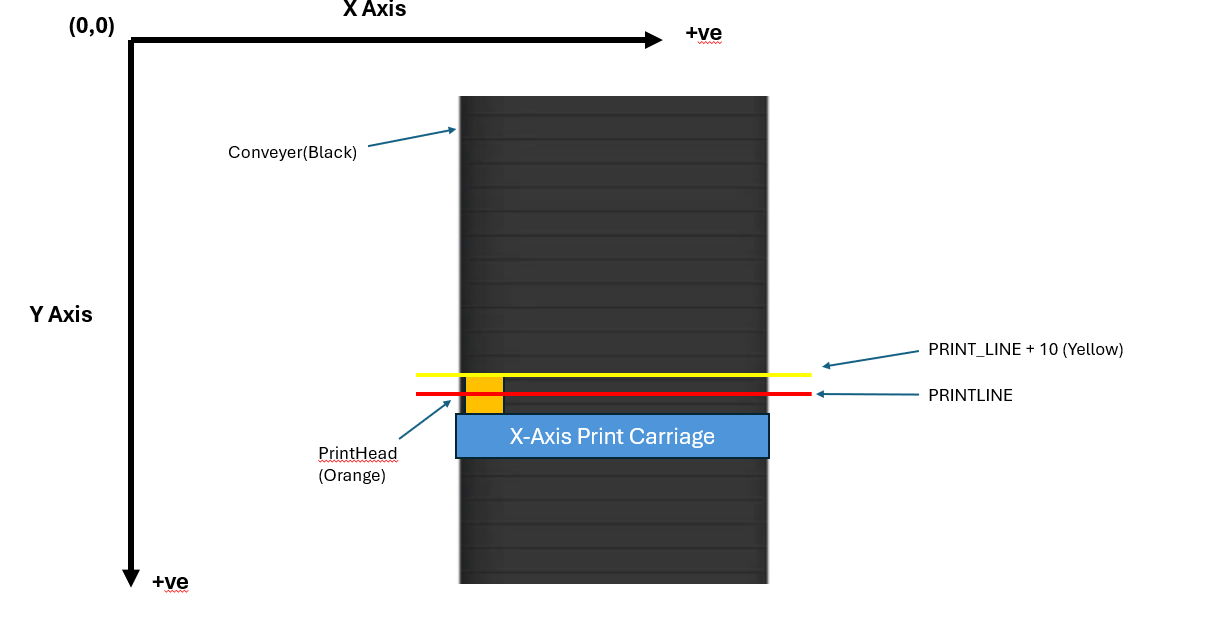
The Pixy2 Camera interprets the conveyor belt based on image recognition. These objects are artisanal pastries, with colour signature boxes on them. Based on the axes, towards the right, the X value increases. As you go down, the Y value increases.
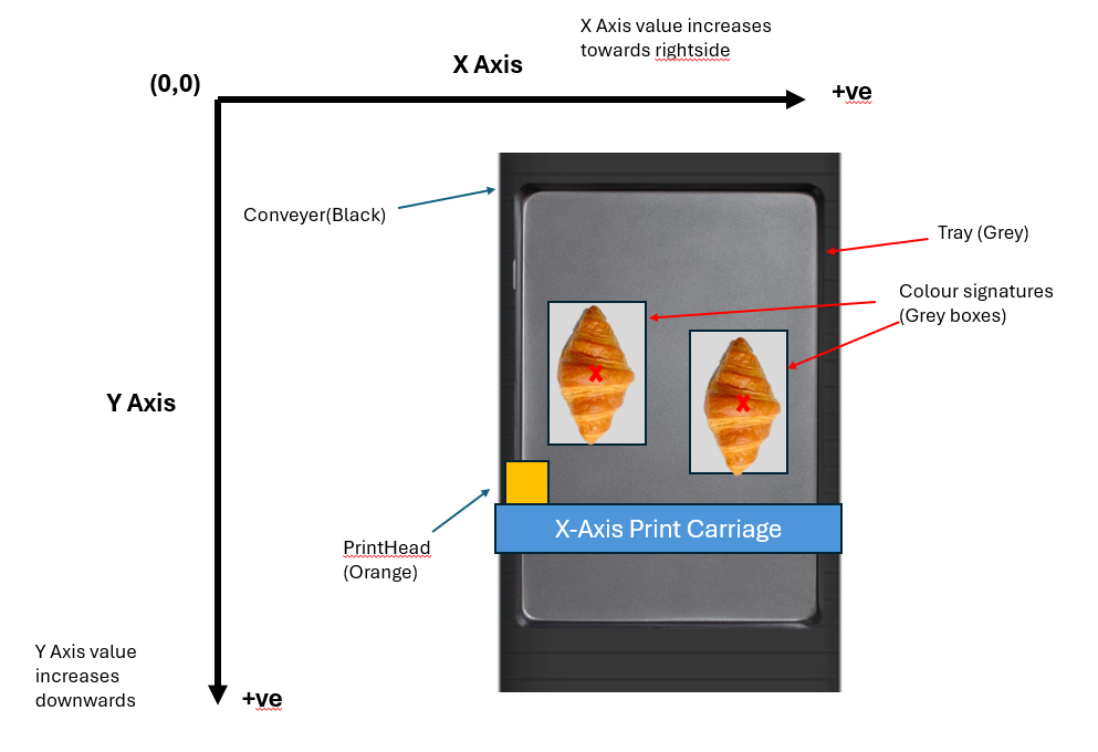
The Pixy camera has two lines to create a row of objects along the X-Axis.
Row Object
Creating a Row Reference Point
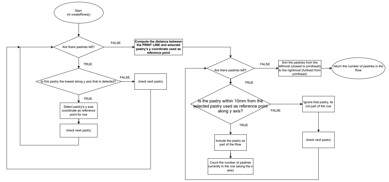
To guide X and Y Axes to move and print on the correct pastries, the program creates a Row, which consists of X coordinates of pastries along the same row, a Y coordinate coordRow_Y serving as a reference point to bring the Row to the PRINTLINE, and the number of pastries/objects in the Row.
typedef struct __row{
    uint16_t coordRow_Y;
    uint16_t numberOfRowObjects;
    uint16_t coordXArray[10];
} Row;
The program creates a reference point for a Row, as described in the code snippet below. The bottommost pastry, i.e., the pastry closest to the PRINTLINE, is the reference point for a Row.
for(int j = 0; j rowval && pastry[j].bottomY <= EVENT_HORIZON) // EVENT_HORIZON is PRINTLINE - 10 pixels (Before PRINTLINE, hence subtract)
    {
        rowval = pastry[j].coordY;
    }
}
The program first finds the pastry closest to the PRINTLINE, i.e., the bottommost pastry along the Y-Axis, by looking at the centre points of these pastries. The bottommost pastry is selected at the end of the for loop. This is the program's first condition.
The second condition dictates that the pastry selected as the reference for the Row must have its bottom width before the PRINT_LINE + 10 pixels line.
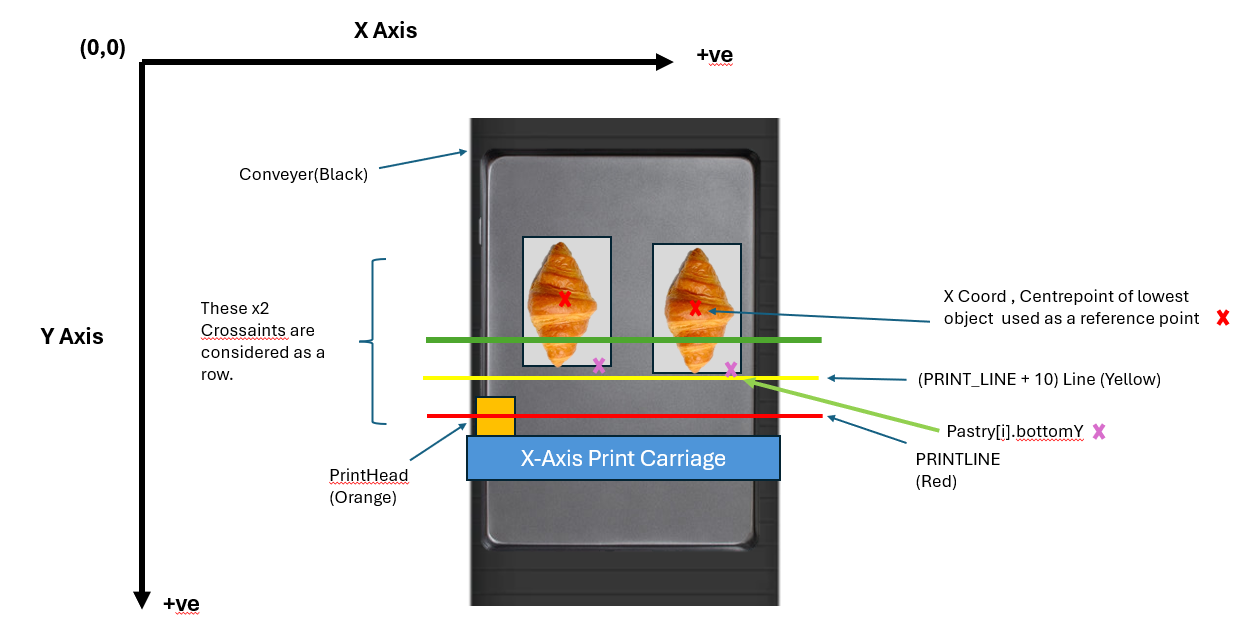
The image above describes a row being created because it meets the two conditions mentioned.
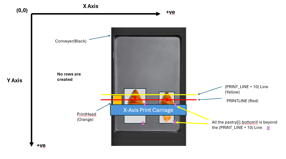
The image above shows that no row is created because it does not meet the second condition.
Adding Pastries to the Row Object
Once the Row reference point is selected, i.e., closest to the PRINT_LINE, the program now adds other pastries along the Y-Axis within a set buffer.
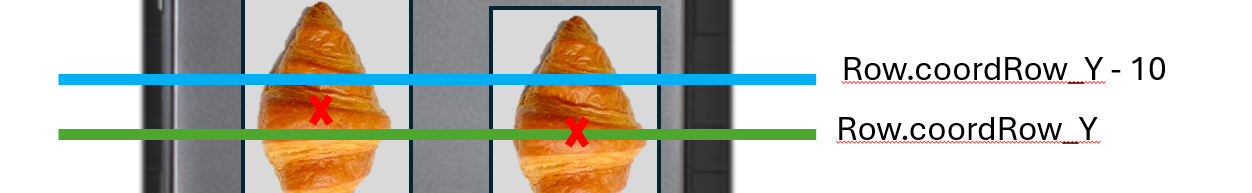
Taking Row.coordRow_Y, which was set as a reference point along the Y-Axis, i.e., conveyor, the program looks for pastries with centre points within Row.coordRow_Y and Row.coordRow_Y - 10. The snippet describes this pastry selection for the Row object.
for(int i = 0; i < numberOfBlocks; ++i) // loop for the no objects
{
    // since the lowest centrepoint is the reference for the row,
    // we account for objects within the gap
    // before the lowest centrepoint
    if(pastry[i].coordY >= (rowval - 10) && pastry[i].coordY <= rowval) {
        row.coordXArray[i] = pastry[i].coordX;
        row.numberOfRowObjects++;
    }
}
Hence, a row is created with the Row.coordXArray[] filled with the centre points of pastries along the X-Axis.
Sorting the Row.coordXArray[]
The row of X coordinates is sorted from smallest (closest to the origin or printhead) to the largest. This ensures that the printhead goes in proper sequence from left to right.
bubbleSort(row.coordXArray, 10);X-Axis Print Head Movement
The X-Axis Movement has the following key functions to guide the printhead to locations where the pastry is placed based on the pixy camera.
printHeadMovementRoutine_AUTO()printHeadMovementRoutine_Manual()
Both of these functions share the same sequence, except that printHeadMovementRoutine_Manual() does not have pressEveBot(), therefore requiring a human to press within a 3 seconds window given.
These two functions execute a logical sequence, calling helper functions shown in the following diagram below:
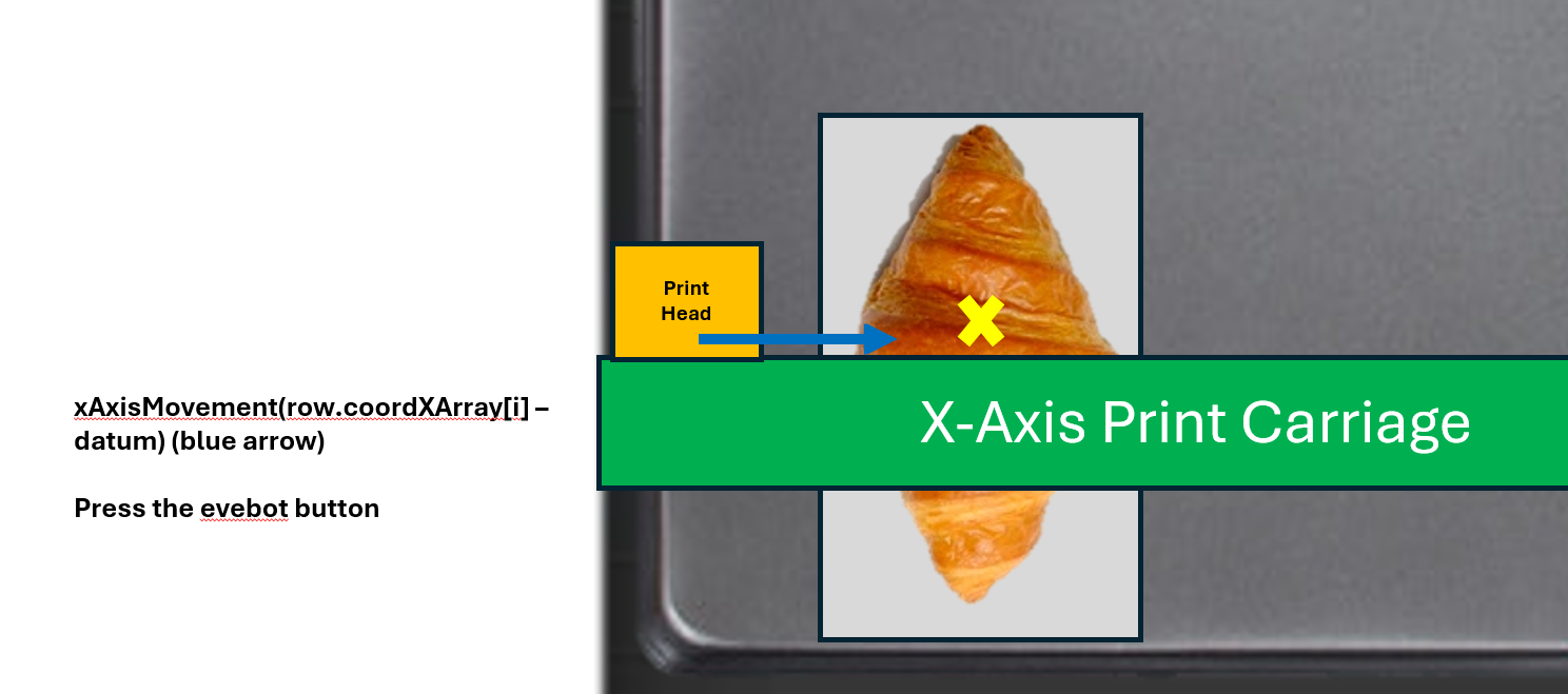
xAxisMovement((row.coordXArray[i] - datum) * PIXY_RATIO)
The xAxisMovement((row.coordXArray[i] - datum) * PIXY_RATIO) moves the printhead to the centre points of pastries, starting with the first pastry. The datum is a preset value that offsets the printhead from the centre point of a pastry. PIXY_RATIO is a ratio used to convert the number of pixels from (row.coordXArray[i] - datum) into distance (mm).
The diagram below illustrates this function.

iniDelay()
Once arrived at the location within an offset from the centre point of the pastry, the program commences iniDelay(). iniDelay() covers the distance gap EVEBOT is required to roll before actual printing commences. The distance gap was measured from the EVEBOT ruler illustrated below.
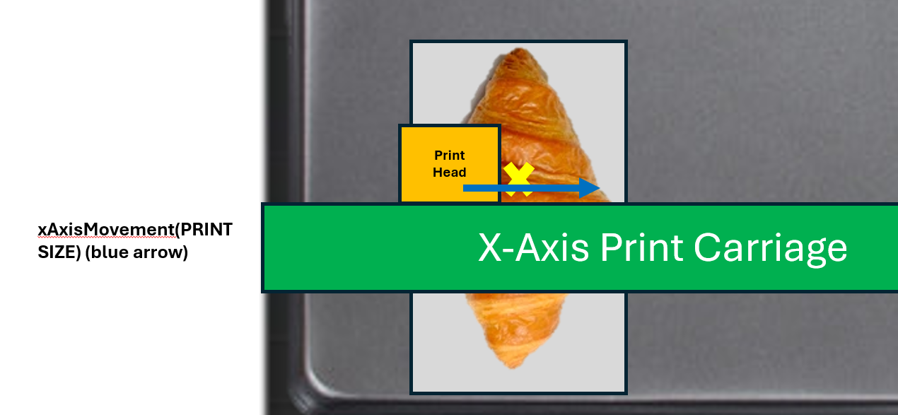
xAxisMovement(PRINTSIZE)
The printhead then moves according to the PRINTSIZE specified by the user via the keypad interface. The default value for PRINTSIZE is 43.
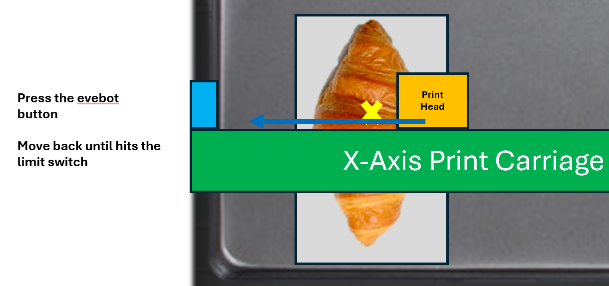
backToHomePosition()
This function moves the printhead back to the HOME position, i.e., until it hits the limit switch at HOME. Within this function, the program sends HIGH and LOW pulses until the limit switch toggles. The following diagram illustrates this:
pressEveBot()
This function sends PWM signals generated by the TIM3 peripheral to the servo motor attached to our mechanical button presser, as shown below. It retracts the pinion presser up, before pressing down and goes back up again.
More information about the Helper Functions
xAxisMovement(int distance)
The function converts the argument that the program assumes into steps for the stepper motor. The steps are for loop iterations, which sends HIGH and LOW pulses in alternating and fixed microseconds interval to the motor driver. This routine is similar to conveyor stepper motor and Z-Axis stepper motor movement, except with differing values. The following code below showcases this:
void xAxisMovement(int distance){
    int dist = distCal(distance);
    int stepDelay = 1900;
    for(int x = 0; x < dist; ++x)
    {
        HAL_GPIO_TogglePin(PRINTHEAD_STEP_PORT, PRINTHEAD_STEP_PIN);
        microDelay(stepDelay);
    }
}
pressEveBot()
The STM32F103RB is configured to generate PWM signals at 50HZ.
__HAL_TIM_SET_COMPARE(&htim3, TIM_CHANNEL_3, RETRACT_PEN_UP);
HAL_Delay(500);
__HAL_TIM_SET_COMPARE(&htim3, TIM_CHANNEL_3, EXTEND_PEN_DOWN);
HAL_Delay(500);
__HAL_TIM_SET_COMPARE(&htim3, TIM_CHANNEL_3, RETRACT_PEN_UP);
HAL_Delay(500);
The __HAL_TIM_SET_COMPARE() describes TIM3 being used, while the third parameter is the duty cycle you would like to set. Since the counter period is set to 1000 on the STM, RETRACT_PEN_UP and EXTEND_PEN_DOWN are given values of 200 and 336 respectively. That means divided by the counter period, duty cycles are 20% and 36% respectively.
Y-Axis Print Head Movement
The Y-Axis Movement has the following key functions to guide and move the conveyor belt to move the tray of pastries along the Y-Axis.
conveyorMovement(int z)
Similar to xAxisMovement(int distance), the function moves the conveyor stepper motor, as specified by int z (distance in mm).
conveyorMovePastry()
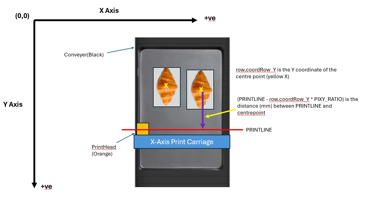
This function additionally computes the distance required to move the reference point of a row to the PRINTLINE.
row.coordRow_Y is the difference in distance in pixels between the PRINTLINE and the y coordinate of the row reference point, i.e., the lowest pastry in the row. The following code snippet and a visual diagram illustrate this.
void conveyorMovePastry(){
    int distanceToTravel = row.coordRow_Y * PIXY_RATIO;
    conveyorMovement(distanceToTravel);
}
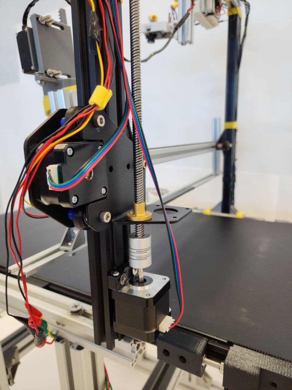
Z-Axis Print Head Movement
The Z-Axis Movement moves the print carriage vertically (upwards or downwards). The diagram below shows where the Z-Axis stepper motor and guiding rod is at:
void moveZAxisUp()void moveZAxisDown()
void moveZAxisUp(){
    int conveyorStepperDelay = 2000;
    GPIO_PinState zAxisDirectionStatus = HAL_GPIO_ReadPin(GPIOC, DIR_Z_AXIS_Pin);
    if(zAxisDirectionStatus == GPIO_PIN_RESET){
        HAL_GPIO_TogglePin(GPIOC, DIR_Z_AXIS_Pin);
        HAL_Delay(1);
    }
    HAL_GPIO_TogglePin(GPIOC, STEP_Z_AXIS_Pin);
    microDelay(conveyorStepperDelay);
}
void moveZAxisDown(){
int conveyorStepperDelay = 2000;
GPIO_PinState zAxisDirectionStatus = HAL_GPIO_ReadPin(GPIOC, DIR_Z_AXIS_Pin);
if(zAxisDirectionStatus == GPIO_PIN_SET){
HAL_GPIO_TogglePin(GPIOC, DIR_Z_AXIS_Pin);
HAL_Delay(1);
}
HAL_GPIO_TogglePin(GPIOC, STEP_Z_AXIS_Pin);
microDelay(conveyorStepperDelay);
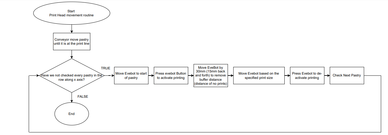
}Final Overview of the X-Axis and Y-Axis PrintHead and Conveyor Movement Routine (Flow Chart)
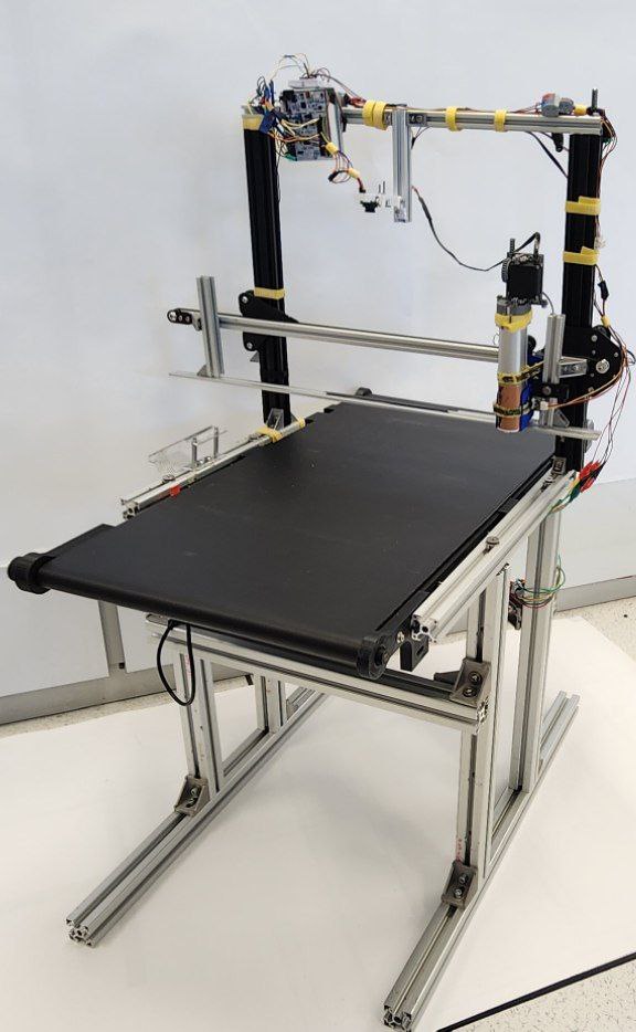
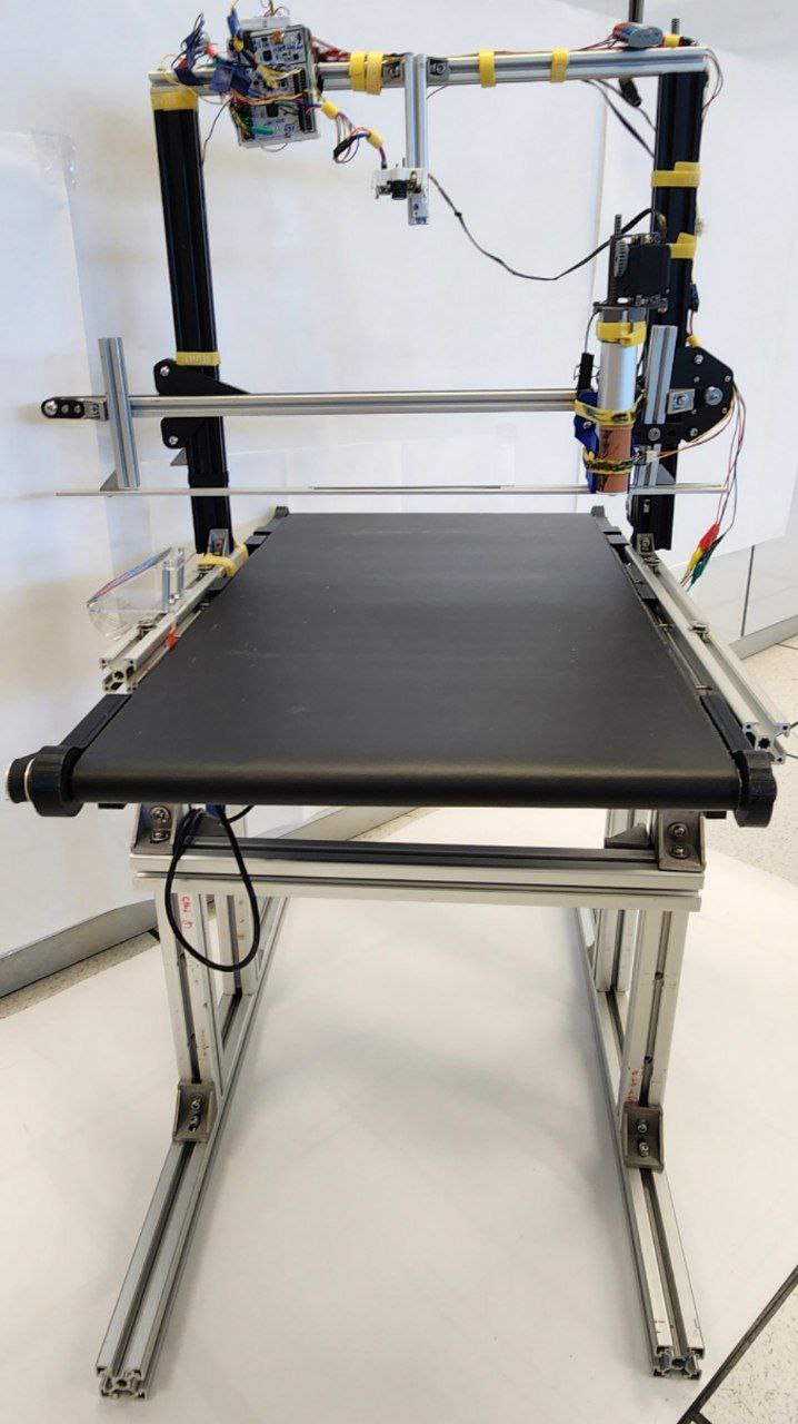
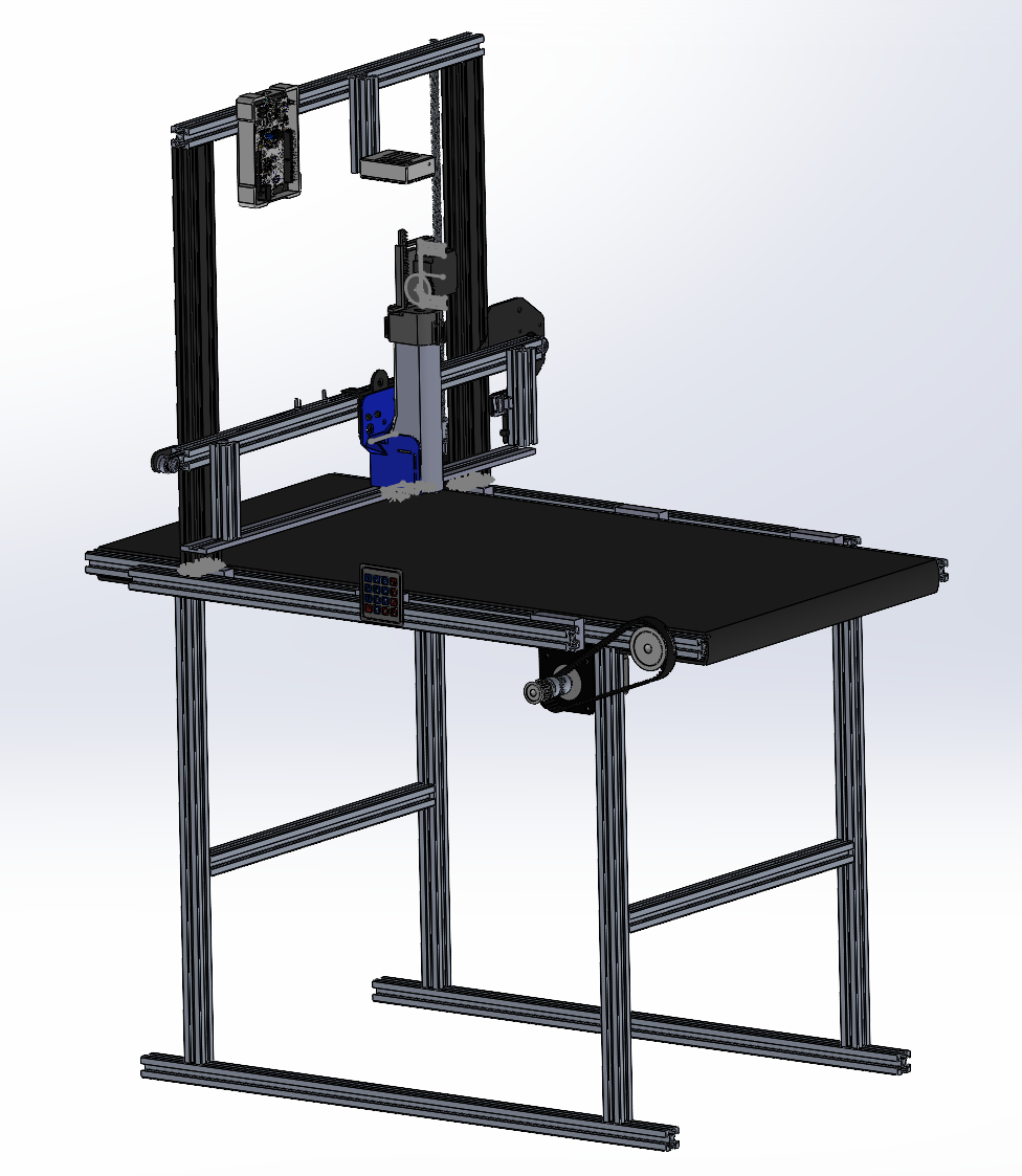
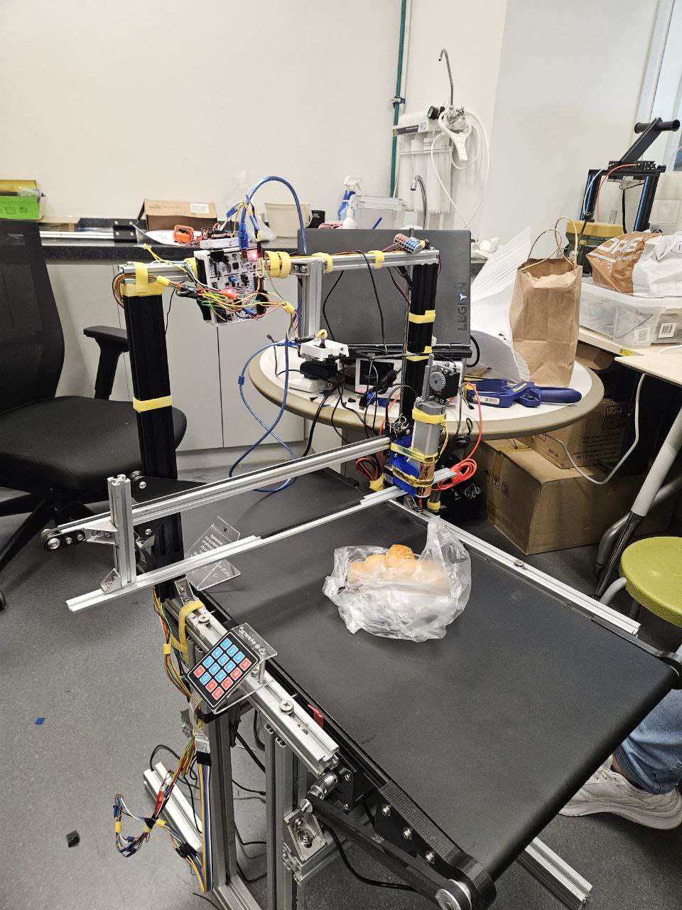
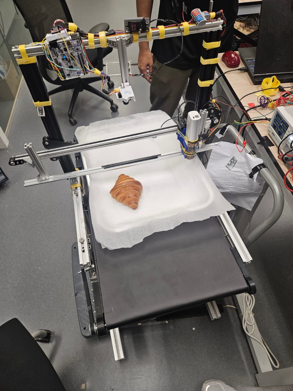
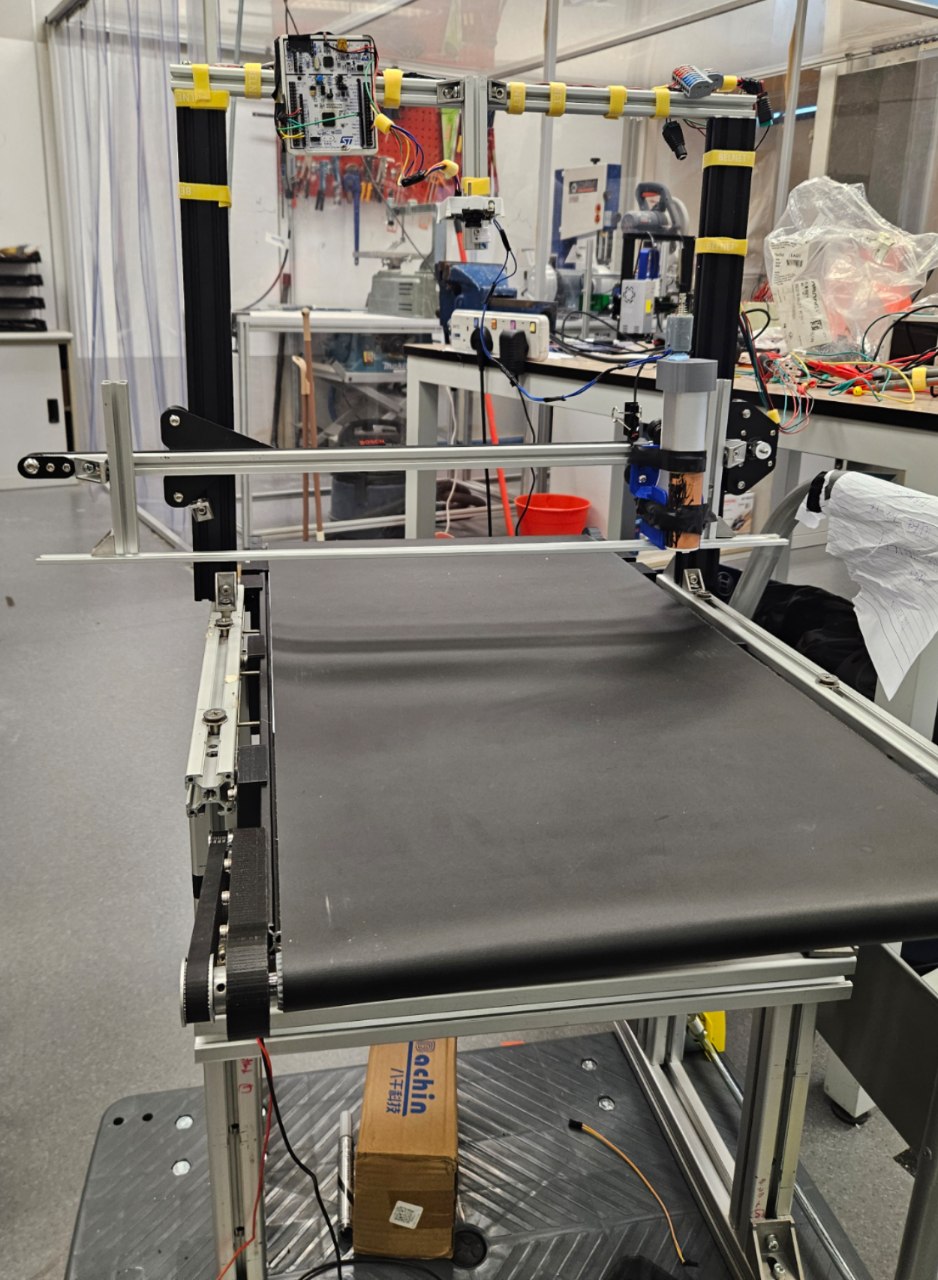
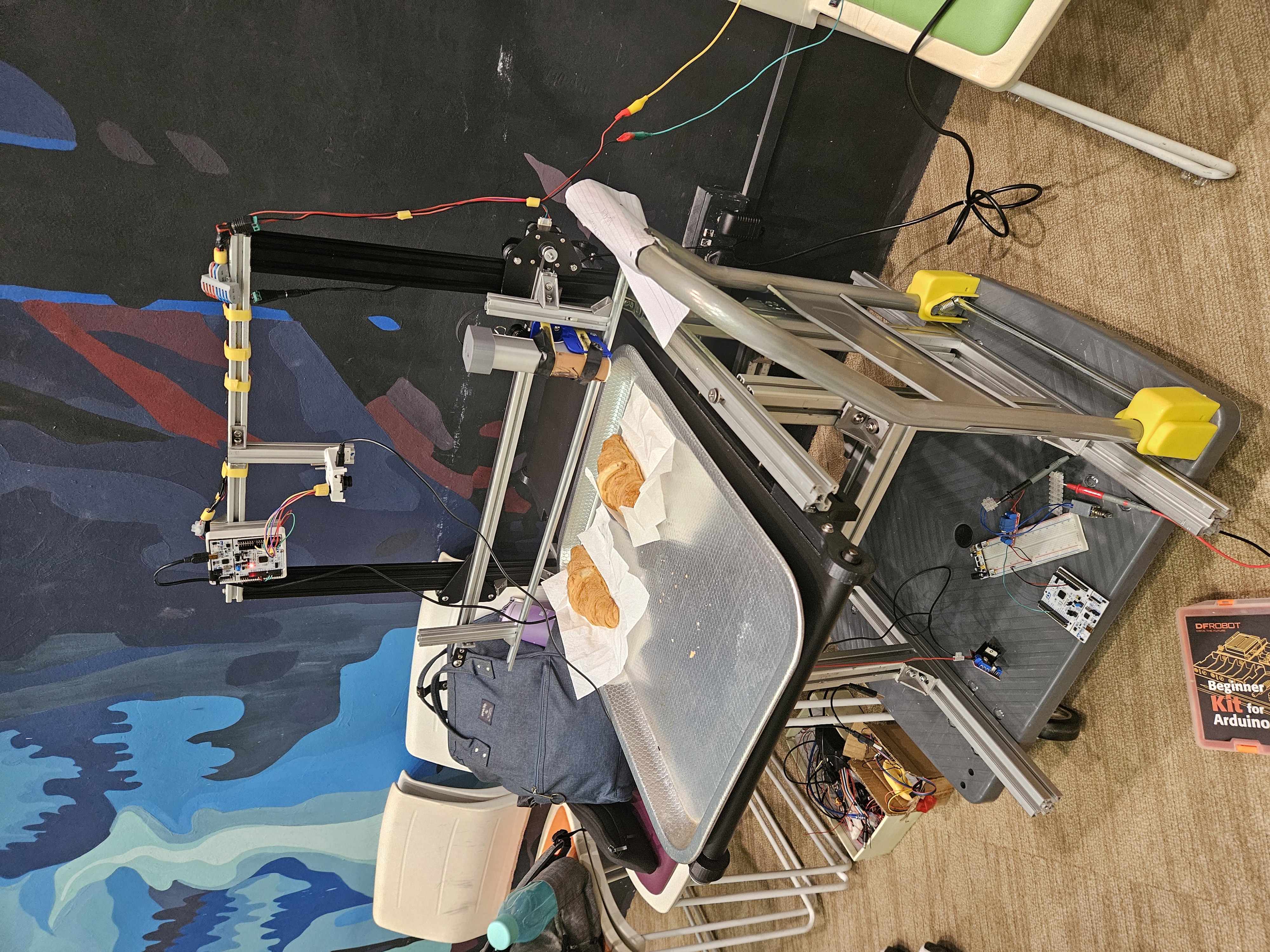
Components of EASY
Isometric view of EASY as a whole.
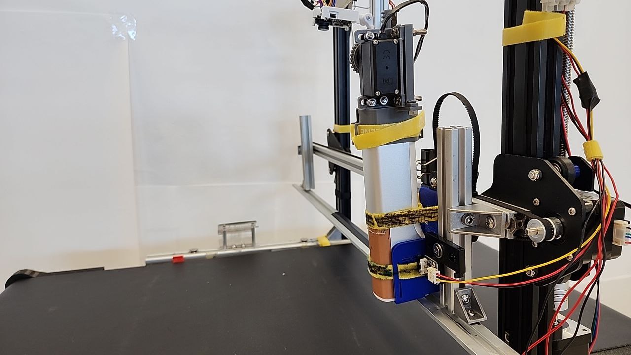
X-Axis of EASY.
Y-Axis of EASY.
Z-Axis of EASY.
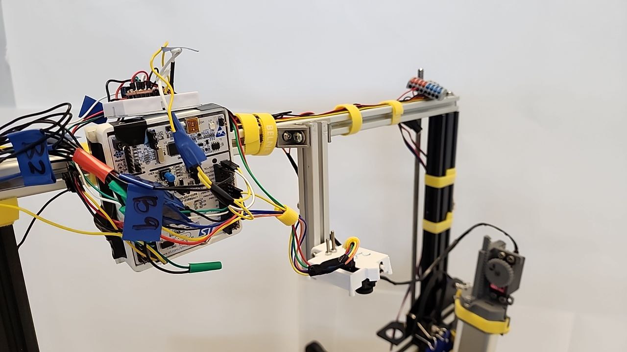
Microcontroller Unit: STM32F103RB and Colour Detection Camera: Pixy2.
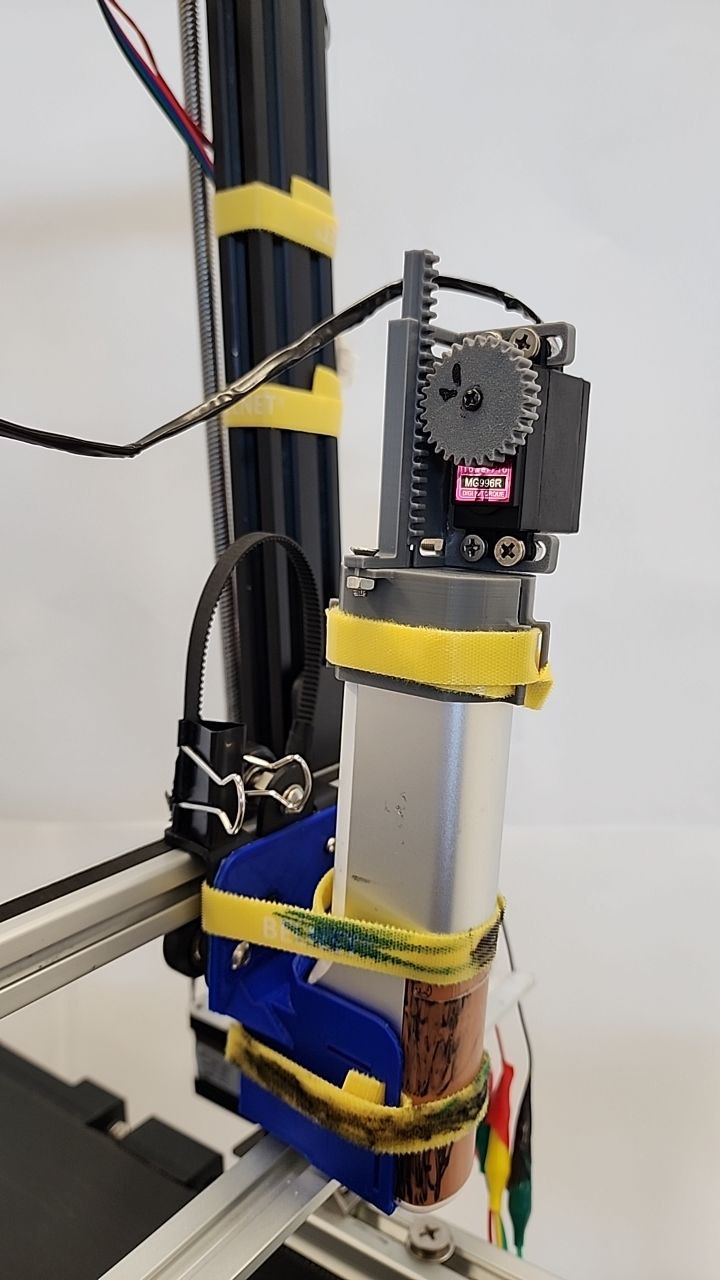
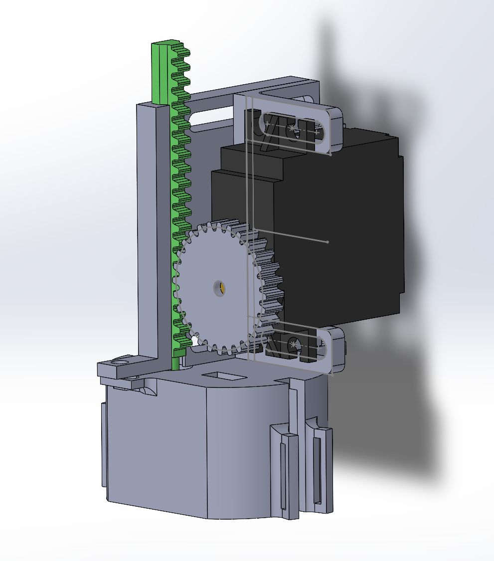
EVEBOT Print Reset Mechanism
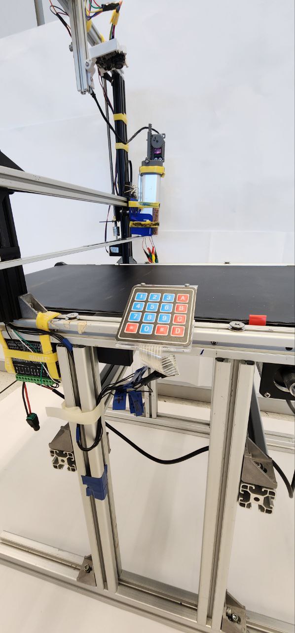
4x4 Keypad for adjusting Z-Axis to fit height of object being printed on.
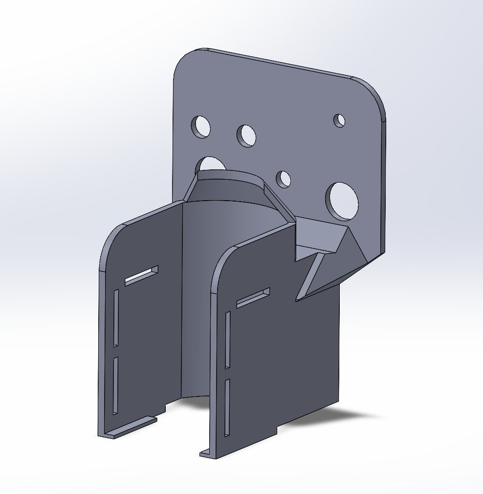
SOLIDWORKS 3D CAD Designs of EASY
Isometric view of EASY
Isometric view of EVEBOT Print Reset Mechanism
Isometric view of EVEBOT Mount
Electrical Diagrams of EASY
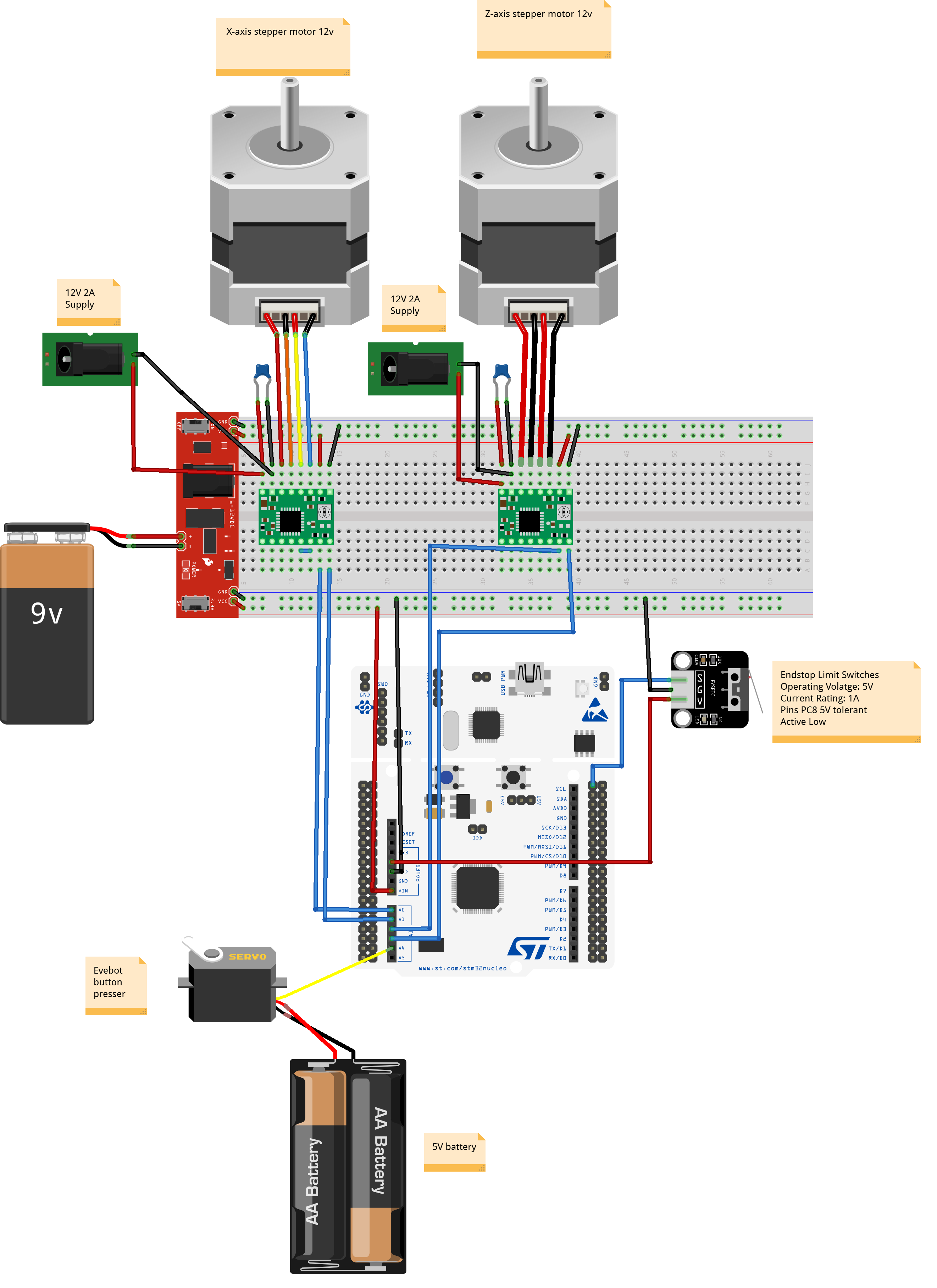
Connections of X-Axis and Z-Axis to A4998 Motor Drivers and MCU.
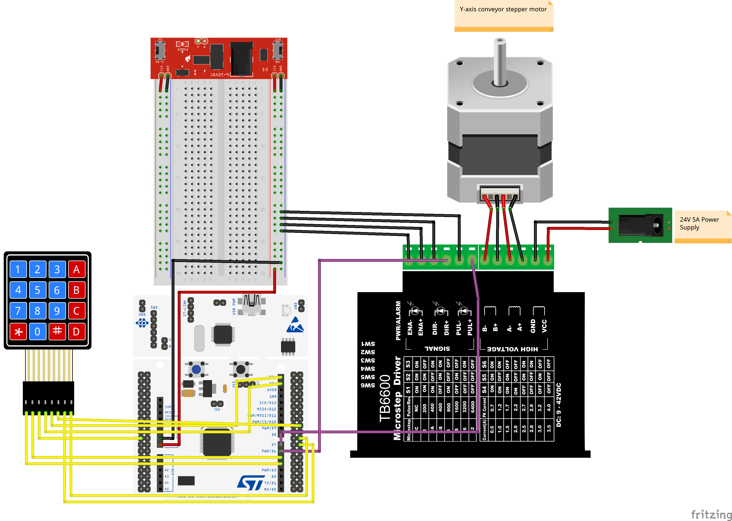
Connections of Y-Axis to TB6600 Motor Driver and MCU.
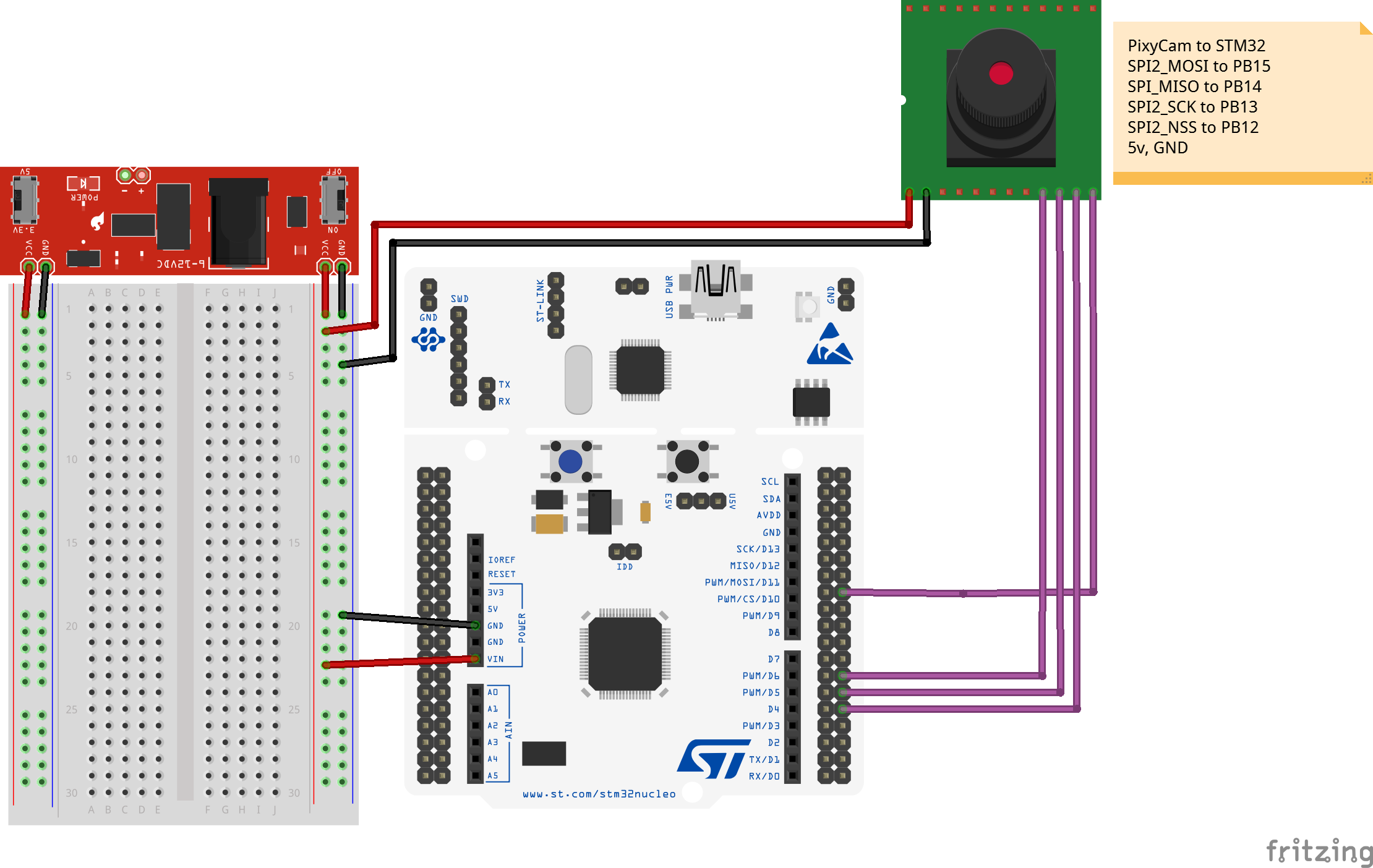
Connections of Pixy2 Camera and 4x4 Keypad to MCU.
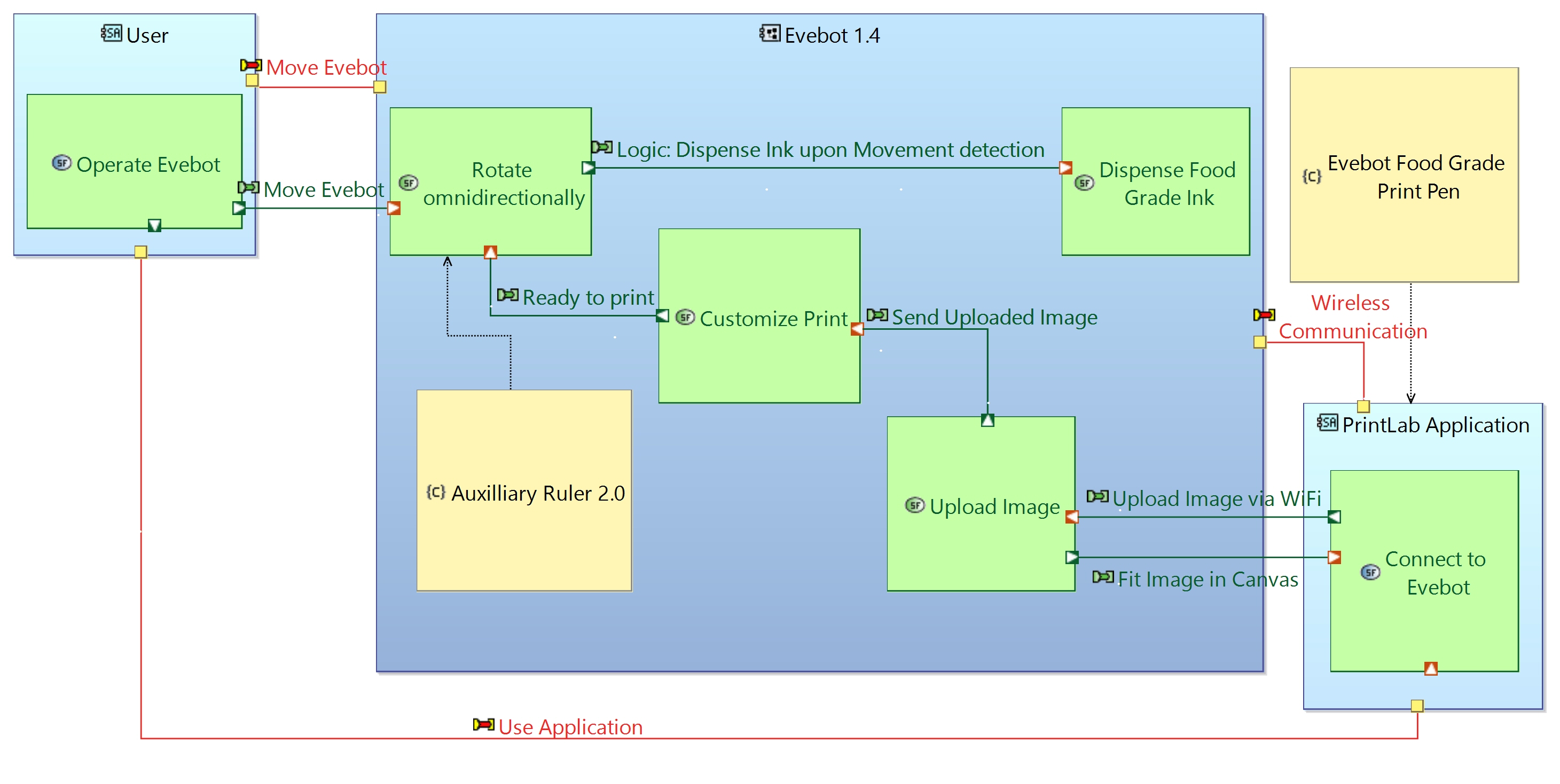
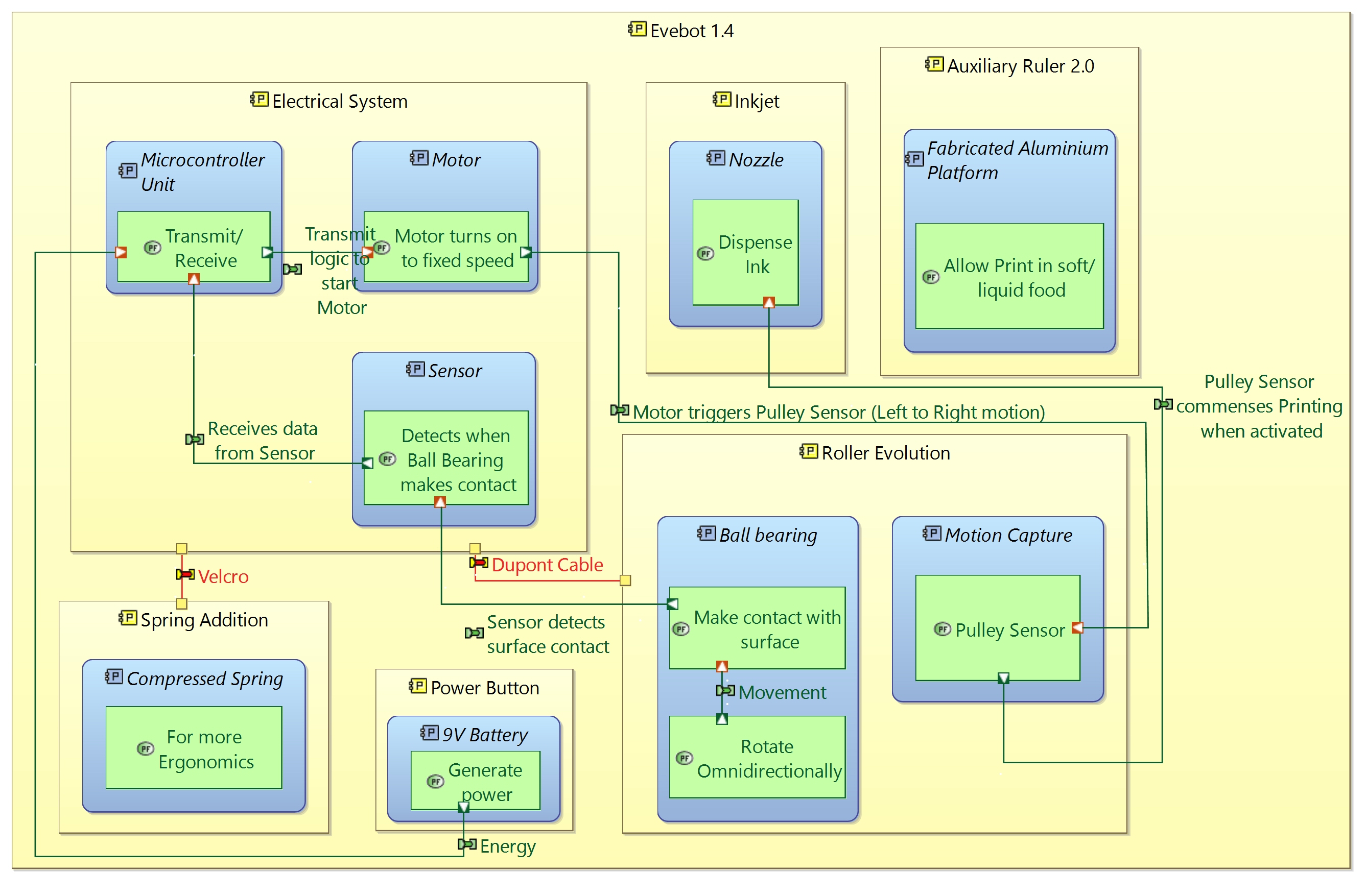
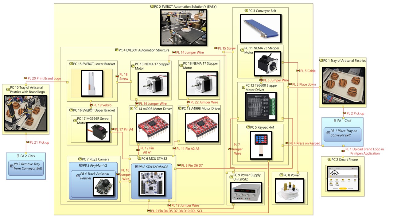
Model-Based Systems Engineering (MBSE)
Utilized Arcadia and Capella Skills to model out Physical Architecture of EASY.
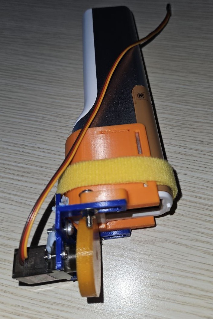
Below are some of the previous iterations of EASY.
Early architecture representations of Ball Point Pen solution which we later decided to terminate to explore other concepts.